Centralised Lubrication System Design Guide
How to size a circuit: point count, dose, pressure class, then the matching pump
Looking for the full parts list?
Every pump and distributor family, with order codes and ratings, is on the products catalogue.
What a centralised oil circuit is
A centralised oil lubrication circuit is four parts in one order: a pump that draws from a reservoir and pressurises a main line, a distributor that decides how much oil each point receives, tube that carries it, and a fitting that delivers it. Everything in this catalogue is one of those four. The three circuit types below differ only in how the distributor meters.
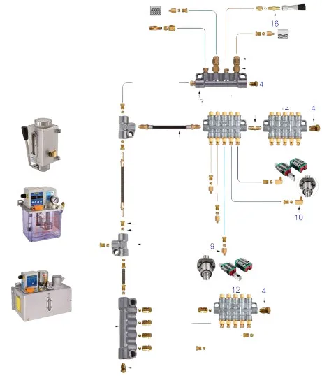
Reading the circuit
The pump sits at the reservoir and feeds one main line. Distributors tap that line in groups; each outlet then runs to exactly one point. Nothing branches after a distributor outlet: one outlet, one point, always.
Size the circuit from the points backwards: total the dose each point needs per cycle, add the distributors that deliver those doses, then pick a pump whose discharge covers the total at the distributor's action guarantee pressure.
Three pressure classes
A grease circuit is classified by the output pressure of its drive source, and that one number decides everything downstream: which pump, which grease grade, which distributor family, which hose. High, middle and low. Every product in this catalogue belongs to one of the three, and mixing across them is the most common specification error we see.
Progressive
Points are fed one after another from a single pressure source. Full pump pressure reaches every point in turn (nothing is divided), so a progressive circuit will push grease into a bearing that a volumetric circuit cannot.
One blocked point stops the whole assembly and raises pressure until the safety valve opens. That is a feature: the circuit reports its own failure.
Volumetric
Each outlet meters a stated dose per cycle, set at the distributor. Points work independently, so one blocked branch starves one point and leaves the rest running.
Needs a pump with a pressure take-off mechanism: the distributor re-meters only when the main line is relieved. Choose volumetric when doses differ point to point.
Replacing an installed lubrication system?
Send AMAG a photo of the existing pump, distributor or machine nameplate. We will identify the lubrication method and configure the complete AMAG replacement package for your machine.
Complete Catalogues
Every pump, distributor, accessory and fitting we hold, with specifications, model-selection tables and the coding rules for building a model number. Print them or send them to your maintenance team.
Oil Lubrication Catalogue
Motor-driven and manual oil pumps, volumetric and resist-type distributors, fittings and tubing for centralised lubrication of production machinery.
- A · Pumps for oil lubrication
- B · Oil distributors
- C · Lubrication accessories
- D · Fittings & tubing
Grease Lubrication Catalogue
High, middle and low pressure grease pumps, progressive and volumetric distributors, fittings and hose for centralised lubrication of heavy and mobile machinery.
- A · Pumps for grease lubrication
- B · Grease distributors
- C · Filling & service equipment
- D · Fittings & hose
Why Choose Our Lubrication Systems?
The Four Design Steps
Four steps take you from point count to an ordered pump and distributor: count the points, size the dose, pick the metering unit for your pressure class, then match the pump to it.
Key Design Principles
Match Pressure to the Distributor's Window
Each family publishes its own action-guarantee pressure: 8–12 kgf/cm² on the 34-type, 12–15 kgf/cm² on the 35-type and RH3, 1.4–25 MPa on the SD-series. A pump that can't clear that number won't fire the metering elements at all.
Match Viscosity and Grade to the Hardware
Oil distributors accept 20–500 cst; the TCJ/TCZ resist-type family is narrower at 20–50 cst. Grease runs NLGI 000#/00# through a metering chamber, and up to NLGI 2# only where a progressive pump pushes it at full pressure instead.
Design for the Failure Mode You Can Live With
A volumetric point starves silently behind a healthy pressure gauge, unless it's an RH3 with a signal pin. A progressive block stalls the whole distributor and can trip a PLC alarm within minutes. Pick the one whose failure you'll actually catch in time.
System Troubleshooting Guide
Pressure Never Reaches Action Pressure
Potential Causes
- Low reservoir, and check why the level switch didn't alarm
- Suction-side air leak, so the pump churns froth instead of moving lubricant
- Burst or disconnected main line downstream of the pump
- Worn pump no longer making rated pressure
One Point Dry, Others Fine
Potential Causes
- The volumetric architecture's blind spot: each outlet meters independently, so a starved point can hide behind a healthy pressure gauge
- Pinched, kinked or swollen feed tube to that point
- Metering valve jammed by contamination: grit from a dirty top-up or an open reservoir lid is the most common cause
- On an RH3, a signal pin that doesn't move on a commanded cycle points straight at the fault
Progressive Block Stalled or Cycle Alarm
Potential Causes
- One blocked outlet: the pistons fire in strict sequence, so a single jam stalls the whole distributor
- Supply pressure below the SD-series' 1.4 MPa starting threshold, which can mimic a blocked point
- Crack outlet fittings one at a time with the pump running; cycling resumes the moment the blocked line opens
Design Resources & Support
Design Worksheet
Use our comprehensive design worksheet to document your lubrication points, calculate volumes, and select appropriate components.
Start WorksheetExpert Consultation
Our team of lubrication specialists can review your system requirements and recommend the optimal configuration for your equipment.
WhatsApp a specialistFittings & Accessories
Complete range of high-pressure fittings, hoses, tubes, and connectors for grease lubrication systems. Available as individual spares or as kits. Contact us for kit configurations.
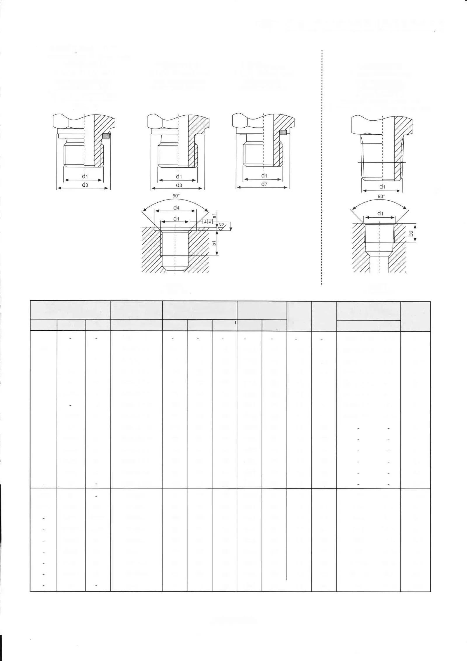
The full catalogue grids have pages of their own: fittings & tubing and lubrication accessories.
Connectors
T-Type Double Connectors
Double T-connectors in BSP and metric thread sizes for branching grease or oil lines. Steel construction.
- Max pressure: 210 kgf/cm²
- Thread standards: BSP 1/8″ to 3/4″
- Models: T-1/8, T-1/4, T-3/8, T-1/2 series
Plugs
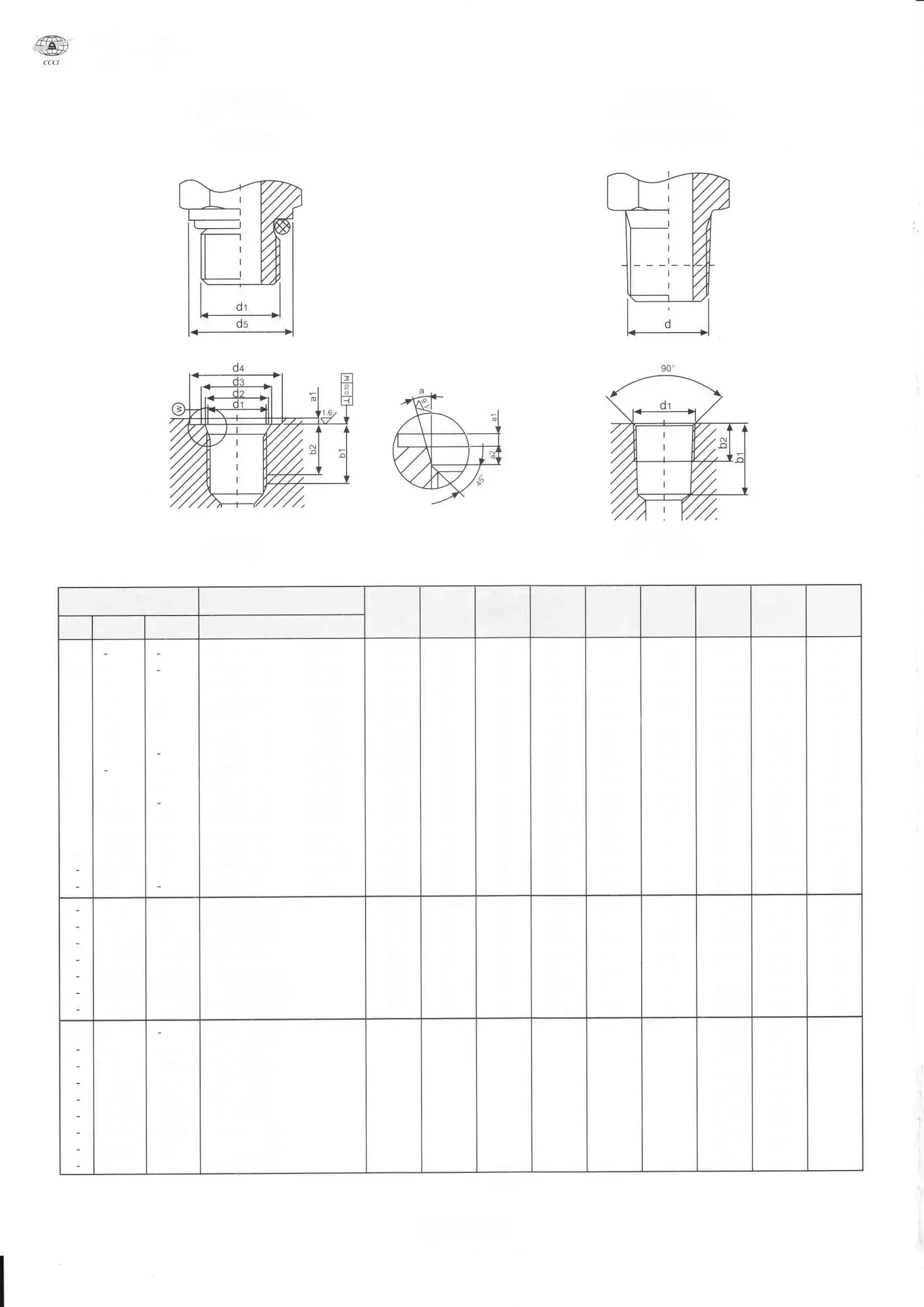
PS-Type End Plugs
High-pressure end plugs for sealing unused ports in distributors, pumps, and manifolds. BSP thread.
- Max pressure: 210 kgf/cm²
- Thread: BSP 1/8″ to 1″
- Models: PS-1/8T, PS-1/4T, PS-3/8T, PS-1/2T
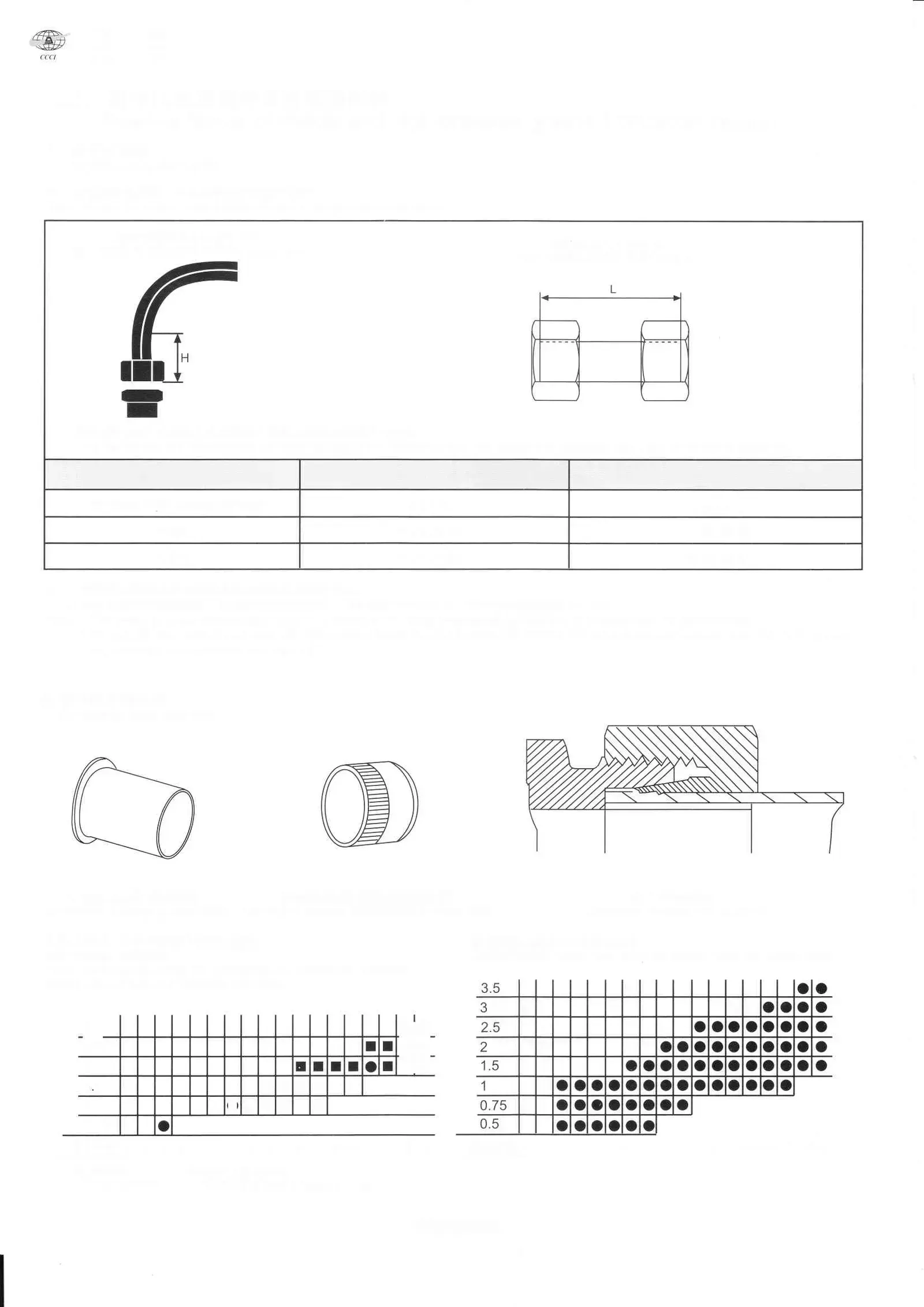
Elbows
PL-Type Elbow Connectors
90° elbow fittings for routing high-pressure grease lines in tight spaces. BSP thread, steel body.
- Max pressure: 210 kgf/cm²
- Thread: BSP G1/8 to G3/8
- Models: PL-G1818T, PL-G1418T, PL-G1414T
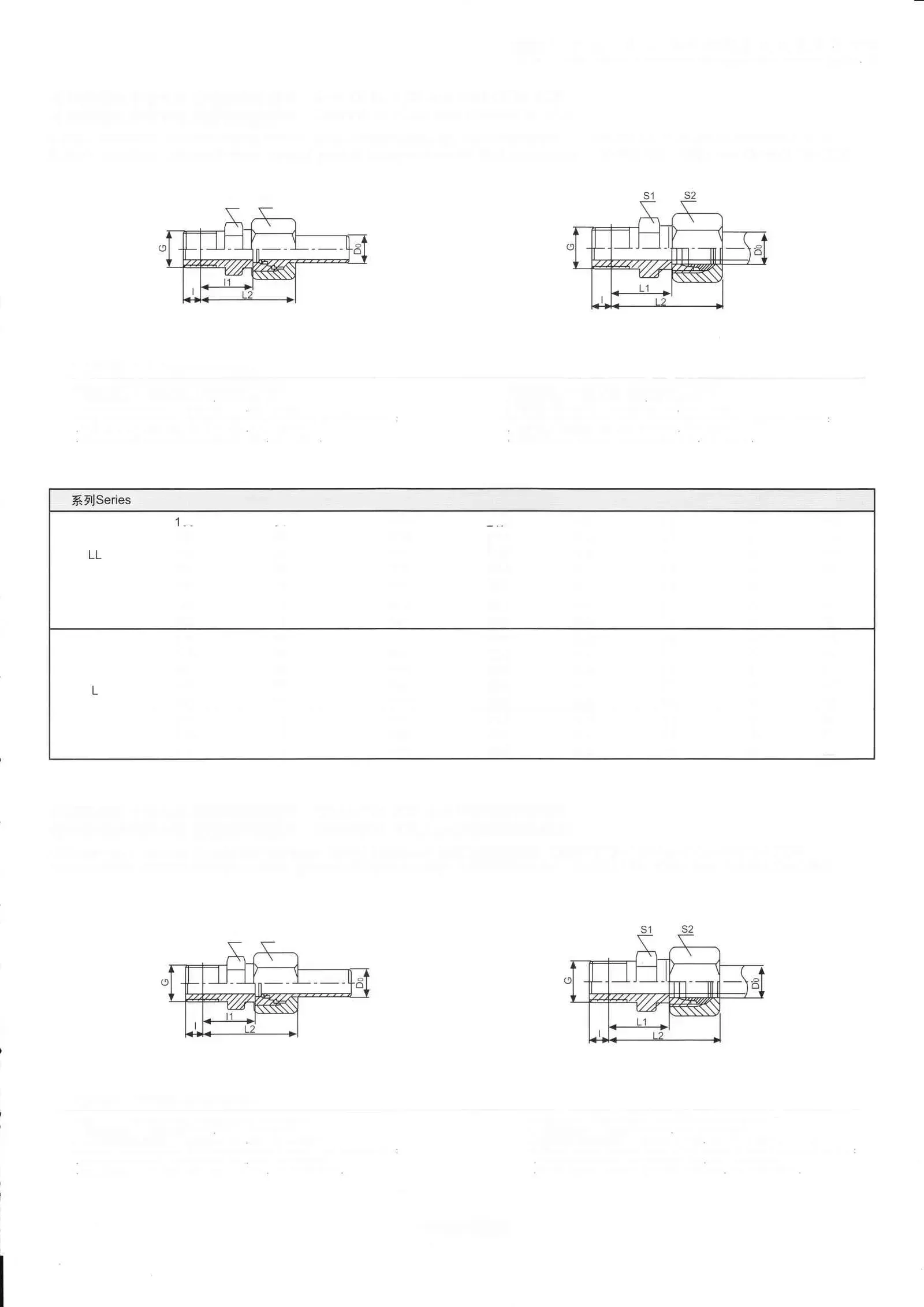
Tubing
SZG High-Pressure Resin Tube
Flexible high-pressure resin tubing for grease lubrication line runs. Resistant to wide temperature extremes.
- Max pressure: 210 kgf/cm²
- Temp range: -30°C to +100°C
- Models: SZG-12, SZG-1414, SZG-118 series
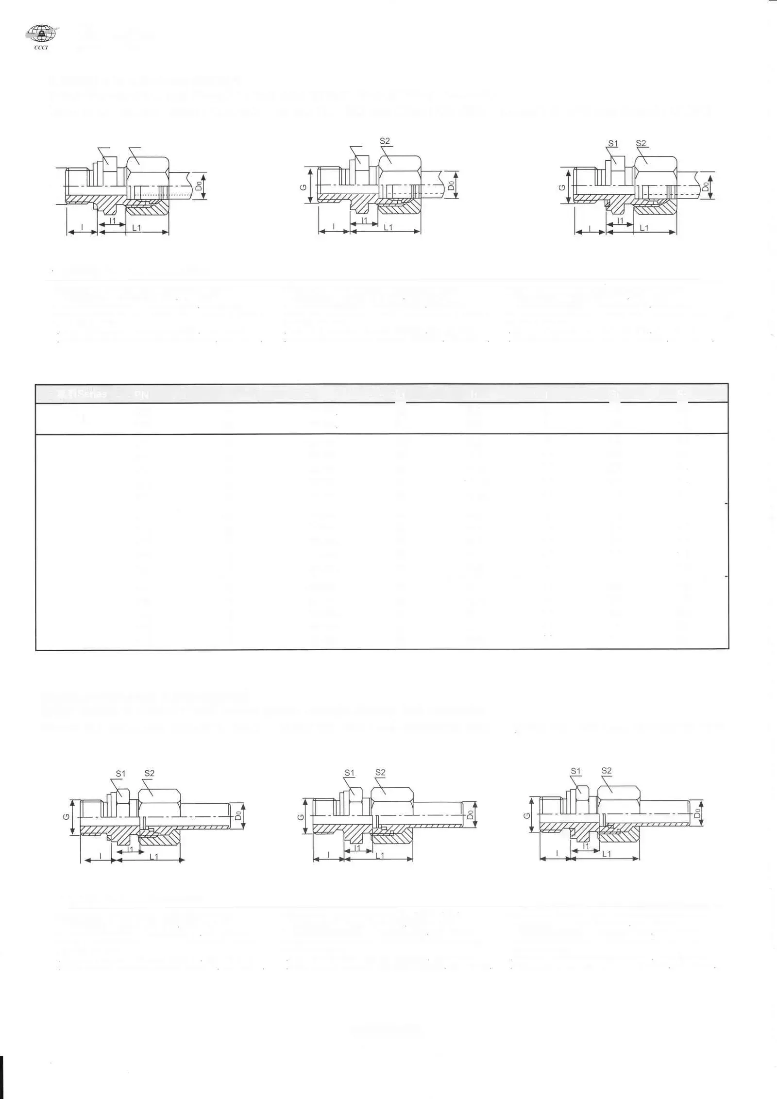
Hoses
HXG High-Pressure Hoses
Reinforced high-pressure hoses for flexible grease line connections to moving machine components.
- HXG-6: inner Ø4mm, 210 kgf/cm²
- HXG-8: inner Ø6.5mm, 255 kgf/cm²
- HXG-10: inner Ø7.9mm, 350 kgf/cm²

Hose fittings
HGJ Straight Expansion Cores
Straight hose end fittings for terminating HXG high-pressure hoses. Available in steel and stainless steel.
- For Ø8.6×4 hose (HXG-6 series)
- Steel and stainless steel variants
- BSP and metric thread ends
Need a fitting kit or spare parts order?
We supply individual spares and pre-configured kits. Contact us with your system details.
Frequently Asked Questions
What is a CNC lubrication system?
A centralised CNC lubrication system delivers metered oil or grease to every wear point (spindle bearings, way guides, ballscrew nuts, tool changer) on a fixed cycle instead of by hand. It is four parts ordered together: a pump that pressurises a main line, a distributor that meters how much each point receives, tubing, and fittings.
How do I lay out a CNC lubrication system?
Four steps: count every lubrication point on the actual machine, not the drawing, calculate lubricant volume from dose times cycle frequency, select a metering unit rated for your pressure class, then size the pump to that distributor's pressure window. The design guide below walks a worked 17-point example, or use the design worksheet to document your own machine.
What does lubrication system design and build involve?
Design is matching a metering unit and pump to your point count, pressure class and lubricant grade. Build is us configuring the matched pump, distributor, tubing and fittings as one order from stock. Send the machine, the point count and the interval, and our engineers confirm the configuration before it ships.
How do I choose a lubrication pump for a CNC machine?
Match the pump's rated pressure to the distributor's action-pressure window: the TZ and HL pumps run 15 kgf/cm² rated (25 kgf/cm² max) for oil circuits on the 34-type and 35-type distributors, while the GM pump is built to 35 kgf/cm² specifically for the 35-type's grease window. All three ship with a reservoir level switch as standard.
Ready to Optimise Your Lubrication?
Send the machine, the lube-point count and the interval. We name the pump and the matching distributors.