Maintenance
Commissioning a Lubrication System: From First Fill to First Cycle
AMAG Team7 min read
The hour spent commissioning a lubrication system decides whether it protects the machine or just decorates it. A system filled clean, bled solid, and proven point by point will do its job for years. One bolted on and switched on will look identical (pump humming, gauge climbing) while a point that never got connected runs dry from day one. The hardware is the same either way; the sequence below is what differs.
This is the order we commission in, with the reasoning behind each step, and a bare checklist at the end to print and take to the machine.
1. Cleanliness before anything else
Contamination introduced on day one lives in the metering valves forever. These are precision parts, dosing fractions of a milliliter, with no filter between your funnel and their tolerances.
In practice: tube and fittings stay capped until cut and installed, and anything that sat open on a dusty shelf gets blown out first. Fill the reservoir through a clean, dedicated container, not the communal funnel that did hydraulic oil yesterday, with the correct grade from the builder's documentation.
If that's vague or missing, reason it out rather than guessing. Our machine-tool oil viscosity guide covers how the grades differ and why slideways want what they want.
Close the lid. It sounds trivial, but it's one of the biggest factors in whether the metering valves are still clean five years from now.
2. Routing and mechanical checks
Before any oil moves, walk every tube run with your hands, not just your eyes.
Look for pinch points: places where a guard, cover, or cable-tie saddle will press on the tube once reassembled. A tube merely touching sheet metal today gets crushed flat once torqued down. Also check for heat near motors or hot chip zones, and for spots that need a drip loop so fluid tracks away from fittings instead of into them. Most of what you find here was decided at layout time; our layout guide covers routing a circuit that survives the covers going back on.
Respect the distributor's tube specification where one exists. The SD2 progressive block specifies an optimum feed tube of Ø6 mm at 1.5–4.5 m, and that range isn't decoration. Long runs add flow resistance and compliance (the tube swells and behaves like a spring), degrading how crisply the block delivers pressure; short runs fall outside its tested conditions. Stay inside the window.
Finally, fittings: snug, not stripped. Soft-material fittings strip easily, and a stripped fitting is a leak you'll chase for months. Tighten to seat, check, and stop. Tube, fittings, connectors, and gauges are listed alongside the pumps and distributors on our lubrication systems page.
3. Priming and bleeding
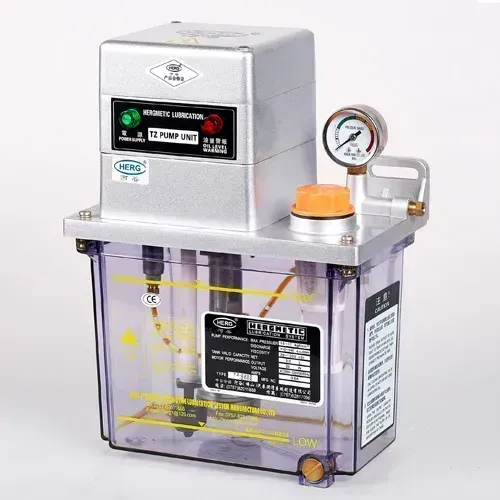 Gauge and level marks on a TZ pump. A smooth, repeatable rise to action pressure is what you're establishing here.
Air is the enemy of the first pressure cycle. Oil is effectively incompressible; air is not. A main line full of air pockets behaves like a spring: the pump strokes, the air compresses, and the gauge staggers and sags.
A volumetric system needs a clean, solid rise to its action guarantee pressure (8–12 kgf/cm² on the 34-type and RH-2, 12–15 kgf/cm² on the 35-type and RH3), or it may never fire its distributors, or fire raggedly. A spongy system isn't just slow, it's unverifiable, because a bleeding problem looks like a real fault.
Bleed deliberately: run the pump, crack the connection at the far end of the main line, and let it discharge until the oil runs solid, no spitting, foam, or bubbles. Close it, run the system again, and watch the gauge; the rise should now be smooth and repeatable. If it still hesitates, check the suction side for the leak.
4. Prove every point once
This step is most often skipped, and it's what separates commissioning from merely installing. A running pump and a correct gauge prove the supply side, nothing about any individual point. A mis-seated outlet fitting, or a tube routed to the wrong point, can hide behind a perfect gauge indefinitely.
So prove delivery physically, once per point. Command a lube cycle and, one point at a time, crack the outlet connection at the bearing end (where oil actually arrives) until oil shows, then move to the next point.
It's tedious on a machine with many points, but it's the only moment you'll verify every point with certainty, and every future diagnosis rests on knowing the system was once fully proven.
If the system uses RH3 inspecting distributors, watch each unit's signal pin extend and retract during the cycle to confirm the metering elements are stroking. Between the pin and oil at the bearing, you have end-to-end proof.
5. Set the schedule deliberately
A lubrication schedule should be a decision, not a leftover. Use the machine builder's manual if it specifies interval and dose. If you're designing it yourself, reason it from point count, per-point dose, and duty, the way we walk through in the sizing worked example, rather than accepting whatever the timer shipped set to.
Write it down where it survives: a card on the machine recording interval, dose, and oil grade. Six months from now, when someone wonders whether the timer setting is original, that card is the answer. It also makes the consumption math checkable, since a reservoir emptying faster or slower than interval × dose predicts is worth investigating.
6. Baseline and handover
Two last measurements turn today's healthy system into a future diagnostic reference.
First, record time-to-pressure: pump start to action pressure, measured now while the system is known-good. Future drift is a useful signal. Slower means air, a leak, or a tired pump; dramatically faster means a blockage trapping the pump against a small volume. Without a baseline, neither drift is visible until it's severe.
Second, prove the alarms by simulation, not inspection. Lift the reservoir level float by hand and confirm the machine annunciates a fault. If a pressure switch is fitted, confirm a lube-pressure fault reaches the control. A switch wired to nothing is decoration, best found out for free on commissioning day rather than during a failure.
Then hand the system over. Show the operator what a normal cycle looks and sounds like, where the level sight is, and what the alarms mean, and put the first inspection on the calendar rather than trusting memory. When something eventually misbehaves, the troubleshooting guide works from the baselines you just recorded.
The checklist
- Tube and fittings stored capped; blown out if in doubt
- Reservoir filled through a clean, dedicated container with the correct grade
- Reservoir lid closed; grade recorded
- Every tube run checked by hand for pinch points, heat, and needed drip loops
- Distributor tube specs respected (e.g. SD2: Ø6 mm, 1.5–4.5 m)
- All fittings snugged, none stripped
- Main line bled at the far end until solid oil, no foam
- Smooth, repeatable rise to action pressure confirmed on the gauge
- Every point cracked at the bearing end and oil confirmed, one by one
- Signal pins (RH3 units) observed cycling
- Timer interval and dose set from the manual or reasoned sizing, not defaults
- Lube card written: interval, dose, grade
- Time-to-pressure baseline recorded
- Level switch (and pressure switch, if fitted) tested by simulated fault
- Operator briefed; first inspection on the calendar
For most machines this is an afternoon's work, and it's cheap reliability insurance. If you're planning a system and want the layout, distributor selection, and doses worked out before commissioning day, start with our design worksheet and we'll engineer it with you.
Related articles
Maintenance
Keeping Wireless Controls Reliable on a Noisy Shop Floor
Why machine shops are hard on radio links, and how receiver placement, cable routing, and honest battery habits keep a wireless pendant dependable.
Maintenance
Troubleshooting a Centralised Lubrication System, Fault by Fault
A symptom-first guide to centralised lubrication faults: pressure problems, dry points, stalled progressive blocks, and alarms that never fire.
Maintenance
Wireless MPG Maintenance and Troubleshooting - Keep Your Controls Working
Routine housing, button and switch care for a wireless MPG pendant, plus fault signatures that trace to the hardware, not the radio link or a dead AA battery.