Technical Guides
CNC Lubrication System Layout: Where the Pump, Lines and Distributors Go
AMAG Team12 min read
Our sizing walkthrough ends with a bill of materials: seventeen points, 2.9 ml a cycle, three manifolds, one TZ pump. It lists layout as a step in the method and then doesn't do it, because sizing and layout are genuinely different jobs. Sizing decides what you buy. Layout decides whether the thing you bought can be filled, read, proved and repaired two years from now by somebody who wasn't there when it went in.
Layout is also the part nobody documents. Distributor datasheets give dimensions and outlet counts. They don't tell you that a manifold bolted face-in behind a bolted cover is a manifold whose signal pins you will never look at again.
Layout is a separate decision from architecture
Architecture is how the dose gets divided: volumetric, progressive, or resist-type, covered in choosing a lubrication architecture. Layout is where the hardware physically sits and how tube runs between it.
The two interact in exactly one place, which we'll come to, but otherwise they're independent. You can build the same seventeen-point volumetric system three different ways with the same parts list and get three different maintenance experiences out of it.
Three layout shapes
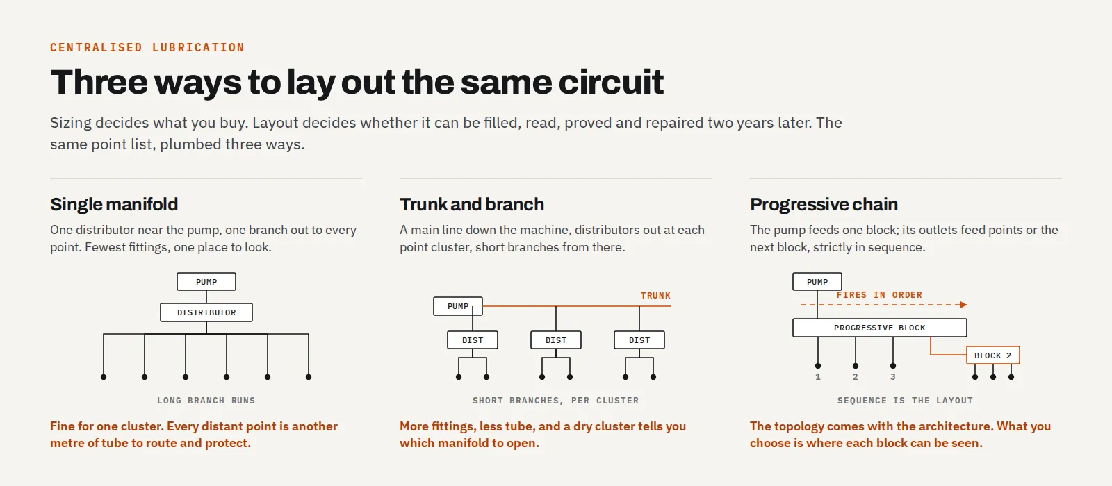
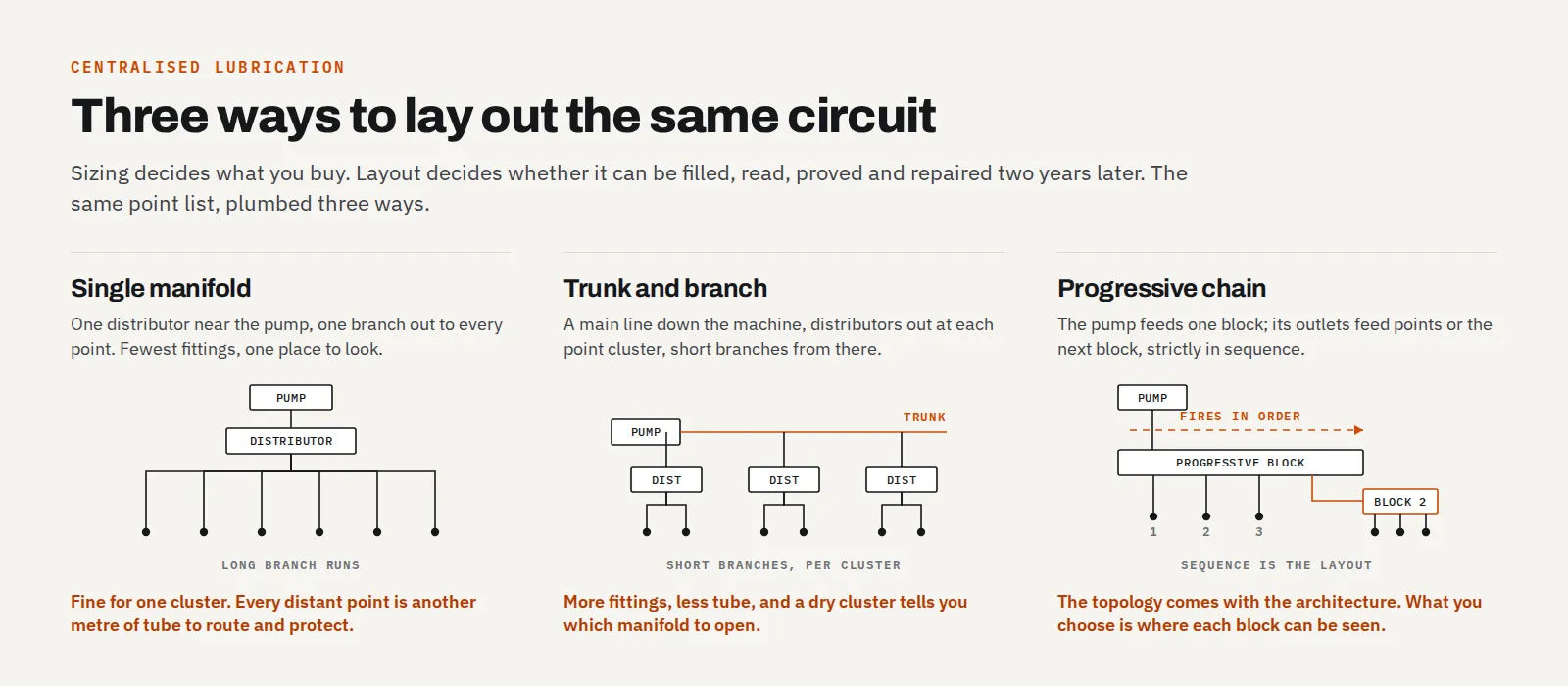 The same points, three topologies. The difference shows up in branch length and in how easily you can isolate one bad point.
Single manifold. One distributor near the pump, one branch radiating out to each point. Fewest fittings, one place to look, and the whole circuit is comprehensible at a glance. It works when the points sit in one cluster: a small machine, a single-axis application, a pump feeding one gearbox. It degrades badly as the machine gets bigger, because every point further away means another long branch run, and a long branch run is another metre of tube to route, clip, and protect.
Trunk and branch. One main line leaves the pump and runs the length of the machine. Distributors sit out at each point cluster, fed off the trunk, with short branches from each distributor to its points. This is the standard layout for a machining centre and the one most builders ship. It costs more fittings, a PA, PB or PT branch fitting to tap each distributor off the trunk, and buys back shorter branches, less total tube, and fault isolation: when one cluster goes dry, you already know which manifold to look at.
Progressive chain. With a series-progressive system the topology isn't really a free choice; the architecture is the layout. The pump feeds one block, and the block's outlets feed points or secondary blocks in sequence. What you do get to choose is where in that chain each block sits, and that choice is worth making deliberately, because the indicator pin or micro-switch on the block is the whole monitoring story.
Where the pump goes
Four constraints, in the order they bite.
The level has to be visible from where somebody stands. A reservoir you can read at a glance, like the HL pump's, turns the level check into something that happens in passing. Mount one inside a panel that nobody opens between services and you've converted a free daily check into an alarm. The level switch still protects you, but it protects you by stopping the machine, which is a worse outcome than a topped-up reservoir.
The fill port has to be reachable without dismantling anything. A reservoir that needs a guard off gets filled late, then rushed, then filled from whatever container is nearest, which is the contamination path that ends up as a jammed metering valve. Convenience here is a reliability feature.
Keep it off the heat and out of the chips. Away from spindle and drive heat, clear of the chip conveyor and the coolant fall. Oil viscosity moves with temperature, and the viscosity window of your distributors is narrower than most people assume, particularly resist-type, at 20 to 50 cSt.
The switches have to reach the control. The level switch should be wired on every installation. If you're fitting the optional pressure switch, at 5 or 10 kgf/cm², it needs a run back to the control too. Decide the pump's position with those cable routes in mind rather than discovering them after the bracket is drilled.
One thing the pump is not: cabinet equipment. It's a machine that holds oil and it belongs on the machine structure, near where the main line leaves for the points.
Sizing the trunk and the branches
Tube for these circuits is nylon in Ø4, Ø6 or Ø8, or copper in Ø4 or Ø6, and the fittings range runs on M10×1 throughout: PA, PB and PT to branch off a main line, PL elbows where a tube can't be bent into a tight point, PD unions to extend a run or adapt into a distributor outlet, and 3T and 4T brass manifolds to split one line three or four ways from a single point.
Diameter follows the port it's feeding, and the rule of thumb is only that the trunk carrying every distributor's supply sizes up from the branches hanging off it. Nylon is the flexible choice for runs that bend around structure; copper is rigid and belongs near heat, where a plastic tube degrades over time. On an existing circuit, follow the builder's original routing rather than substituting one for the other.
Whatever the material, cut it square with a matched tube cutter. A burr from a side-cutter sits exactly where the tube seats into the fitting, and it is one of the more common causes of a blocked point, a failure that looks, from the pump gauge, like nothing at all.
The one place layout and architecture interact
In a volumetric or progressive system, line length does not change the dose. The dose is machined into the metering element. A point at the end of a two-metre branch and a point 150 mm from the manifold get the same volume per cycle, because the geometry decides it and not the resistance (the mechanism). What extra line volume does change is time-to-pressure: more tube means more volume to fill and more elasticity to take up before the line reaches the 12–15 kgf/cm² action pressure that fires the elements. On a long circuit with many distributors, that's the argument for a high-flow pump (TZ standard flow is 110 ml/min at 50 Hz against 220 ml/min high-flow), not the argument for shorter branches.
Resist-type is the exception, and how much of an exception depends on the grade. A calibrated damping hole and the branch it feeds sit in series, so the flow split is set by the pair rather than by the hole alone. When the hole is much the tighter restriction, which is what the design intends, branch length barely registers and you can route as you like. When it isn't, the tube starts taking a share of the ratio, and the short run is over-fed while the long one starves.
Which regime you are in moves with the flow grade. TCJ and TCZ span a 16:1 relative flow across their five grades, and the highest-flow grade is by definition the least restrictive of the five, so it is the one where the tube most easily becomes part of the split. Comparable runs are the safe default everywhere; on a high-grade point they are worth treating as a design constraint. Keep the oil inside the 20 to 50 cSt window, and if a retrofit extends one branch, check what it did to the others rather than assuming the restrictor absorbed it.
Routing rules that survive reassembly
The test for a layout isn't whether it works on commissioning day. It's whether it still works after the first guard comes off and goes back on.
Route for the reassembled machine, not the stripped one. Every cover, guard and cable-tie saddle goes back eventually. A tube merely touching sheet metal with the guard off gets crushed flat once that guard is torqued down. Put the covers back before you sign the installation off; this is on the commissioning checklist for a reason.
Give every crossing to a moving axis a service loop. A tube that flexes right at a fitting fails at that fitting. Anchor both sides of the crossing, leave a generous loop with a bend radius the tube can actually take, and let the loop do the moving.
Clip it so no fitting carries weight. A run that supports its own hanging weight puts that load on the joint at the top. Clip at regular intervals and the fittings only ever see pressure.
Leave a drip loop before fittings in the wet zone. A low point ahead of the connection sends coolant tracking away from the joint instead of into it.
Keep tube out of the chip fall. Hot swarf landing on nylon is not a theoretical problem, and the chip conveyor lip is the single worst place on the machine to run anything.
Put distributors where faults are visible and reachable
This is the part of layout that pays back most, and it costs nothing at design time.
A volumetric distributor tells you almost nothing from the pump end: the gauge confirms the main line held pressure and no more. The RH3's signal pin is the exception: per-outlet mechanical proof that lubricant moved, visible without instruments. Mount it face-in behind sheet metal and the pin still moves, perfectly, where nobody can see it. Treat "can an operator read this from the floor?" as a hard routing constraint.
The same logic applies to progressive blocks. The indicator pin needs a sightline; the micro-switch needs a cable route back to the PLC. Decide both when you're placing the block, not after.
And leave room to work. Proving a point means cracking its fitting with the pump running and watching oil arrive, the only check that confirms delivery at the point rather than at the gauge. That takes a spanner, a swing, and somewhere for the oil to go. A manifold with barely a finger's clearance to a casting is a manifold you will never prove.
Layout choices and what they cost later
| Layout choice | What it costs |
|---|---|
| One manifold at the pump, long branches to every point | Metres of extra tube to route and protect; a blocked branch is a hunt, not a lookup |
| Distributor mounted face-in or behind a bolted cover | Signal pins unreadable, fittings uncrackable; monitoring reverts to the pump gauge |
| Branch fitting teed in at a flexing joint | The fitting fatigues at the one place it can't be inspected |
| Resist-type circuit with mismatched branch runs | Flow ratios drift off design; the short run is over-fed and the long one starves |
| Reservoir readable only with a panel open | The daily level check stops happening; the level switch becomes the check |
| No spare capped outlet | A fourth axis or an added wiper point means a new manifold and a new trunk tap |
| Tube clipped to a loom that gets pulled during service | Somebody's wiring job becomes your lubrication fault |
Laying out the seventeen-point VMC
Take the machine from the sizing example: three axes, twelve guide trucks, three ballscrew nuts, two support bearings, three 6-outlet 35 Type manifolds, one TZ pump.
Trunk and branch, three clusters. The pump goes on the column base at the back of the machine, reservoir facing the aisle the operator walks, fill port clear of the enclosure door swing. A Ø6 trunk leaves the pump and runs the length of the bed, tapped with PA branch fittings at three points: one manifold low on the saddle for the X trucks and screw, one at the table casting for Y, one high on the column head for Z. Branches to the points are the size their ports take, cut square, clipped so the manifold outlets carry no weight.
The Z-axis manifold is the one that needs thought. Its trunk feed crosses onto a moving axis, so that crossing gets a service loop anchored at both ends, sized for full Z travel at the bend radius the tube will tolerate. The manifolds are mounted face-out with a spanner's swing at each outlet, because on a 35 Type that swing is the whole inspection story: it carries no signal pin, so proving a point means cracking its fitting. If you would rather read a pin than crack a fitting on a given cluster, that is the argument for specifying an RH3 there instead, and for mounting it with the pins facing the enclosure window. The eighteenth outlet, the spare from the sizing exercise, is capped on the Z manifold, because if this machine ever gets a fourth axis, that's where it'll be.
Same parts list as the sizing post. Different machine to own.
The short version
Sizing is arithmetic and layout is judgement, which is why layout is the half that gets skipped. Three questions carry most of it: can somebody see the level and the pins, can somebody reach the fittings with a spanner, and does every run survive the covers going back on? If you're planning a system and want the layout worked out alongside the doses and the distributor selection, describe the machine in our design worksheet and we'll engineer it with you, or contact us and we'll go through it directly.
Frequently asked questions
Where should the lubrication pump be mounted on a CNC machine?
On the machine structure, near where the main line leaves for the points, with the reservoir level visible and the fill port reachable without removing a guard. Keep it off the electrical cabinet and away from spindle drive heat and the chip conveyor. A reservoir nobody can see is a reservoir found empty by alarm.
Does a longer lubrication line reduce the dose at that point?
Not in a volumetric or progressive system. The dose is machined into the distributor, so line length changes how long the system takes to reach action pressure, not how much lubricant the point receives. In a resist-type system it does matter, because there the calibrated restrictions and the line itself together set the flow split.
How many lubrication points should one distributor serve?
As many as sit in one physical cluster on the machine. A 35 Type body comes in 2, 3, 5 and 6 outlets and an RH3 in 2 to 5, combinable in series, so match the body to the cluster rather than to the total point count. Several small manifolds near their points beat one large manifold with long branches.
What tube diameter should a lubrication main line be?
Match tube to the port it feeds. Nylon comes in Ø4, Ø6 and Ø8 and copper in Ø4 and Ø6, and PA/PB/PT branch fittings and 3T/4T manifold ports are sized against those diameters. Branches to individual points are usually the smallest size the port takes; the trunk carrying every distributor's supply is sized up from that. Confirm the distributor port size before ordering tube.
Related articles
Technical Guides
When a Centralised Grease System Can Run NLGI 2
NLGI 2 belongs on a 30 MPa progressive circuit, not a GM or 35-type reservoir. The three grease pressure classes decide the grade, and what mixing them costs.
Technical Guides
How to Lubricate an Injection Moulding Machine: Tie Bars, Toggles, and Platens
Oil or semi-fluid grease on the clamp, why those points want pressure-volumetric metering, and the AMAG pump pairings that match a 35-type action window.
Technical Guides
How to Set Up a Wireless MPG: Workflows That Actually Change
Five setup jobs where a wireless MPG changes how you stand and work, from indicating fixtures to first-part proving, and the habits it asks for.