Technical Guides
How to Lubricate an Injection Moulding Machine: Tie Bars, Toggles, and Platens
AMAG Team8 min read
The injection unit on a moulding machine is a plastic problem. The clamp is a lubrication problem. Tie-bar bushings, toggle pins and platen guides take the locking force, cycle every shot, and sit in places a grease gun reaches badly once the guards are on. A machine that is otherwise healthy will score a bushing in a week if one of those points runs dry, and the first sign is often a noisy toggle or a platen that no longer tracks square, not a lube alarm.
Both oil and grease are catalogued for this duty. The builder's spec decides which. What the spec is really choosing is a circuit: a pump that can raise the line to the distributor's action pressure, distributors that meter a fixed dose to each pin and bushing, and a take-off so the chambers refill between shots. This post is that circuit, as AMAG builds it.
The industry page is lubrication for injection moulding machines. What follows is the reasoning behind the pairings on that page.
What you are actually lubricating
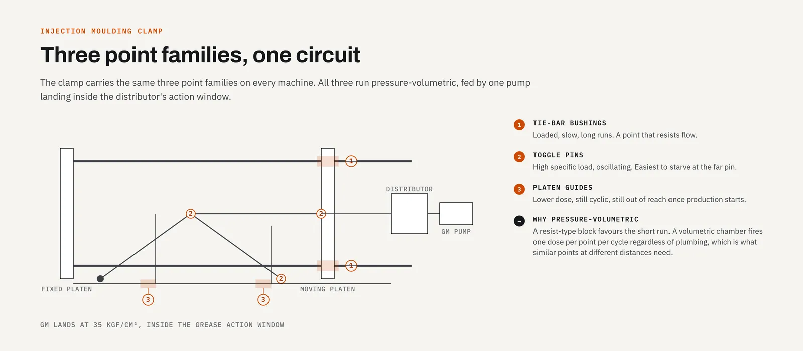
On a horizontal or a vertical machine the clamp carries the same three families of point:
- Tie-bar bushings, where the moving platen slides. Loaded, relatively slow, and long: a point that resists flow.
- Toggle pins (or the equivalent links on a hydro-mechanical clamp). High specific load, oscillating, easy to starve at the far pin if the line is the one that lost the argument with a guard.
- Platen guides and wear plates. Lower dose than a pin, still cyclic, still out of reach once production starts.
These are not slideways on a machining centre. They do not want a scraped oil film you can inspect with a torch after lunch. They want a small, repeated, forced dose at the pin, against real back-pressure, thousands of times a week. That is why the default architecture here is pressure volumetric, not resist-type and not a row of grease nipples.
A resist-type block divides oil by restriction. A short run to a near toggle will take the flow; a long climb to the top tie bar will not. A volumetric chamber does not care which run is easier. One cycle of the pump produces one chamber-full at every outlet, which is the behaviour you want when the points are similar in kind and different in plumbing. The mechanism is in how volumetric distributors work.
Oil or grease is a spec, not a preference
Oil is the lighter circuit. A TZ or HL with the pressure take-off fitted feeds 34-type or 35-type bodies at 8–15 kgf/cm². The 34-type is oil only, 2–5 outlets, 0.03–0.16 ml per outlet, action window 8–12 kgf/cm². The 35-type is 2, 3, 5 or 6 outlets at 0.1–0.6 ml, action 12–15 kgf/cm² on oil, viscosity 20–500 cSt. Use the 34-type on a small machine with light pins; use the 35-type when the pins want the larger dose.
Grease is the circuit most Indian moulding shops already think they have, because the original machine arrived with a grease pump on the clamp. The grade is not the cartridge on the bench. Centralised volumetric grease on this hardware is NLGI 000# or 00# (semi-fluid) for the same reason every other small-bore volumetric grease circuit is: the grease has to slump in the reservoir, travel metres of tube, and fire a metering piston. NLGI 2 channels at the inlet and packs the far lines. That failure is described, including the PLC symptoms, in why centralised systems run 000 and 00.
On grease the 35-type's action window rises to 30–40 kgf/cm². The pump has to land inside that window after line losses, or the outlets do not fire.
The GM pairing exists because the numbers fit
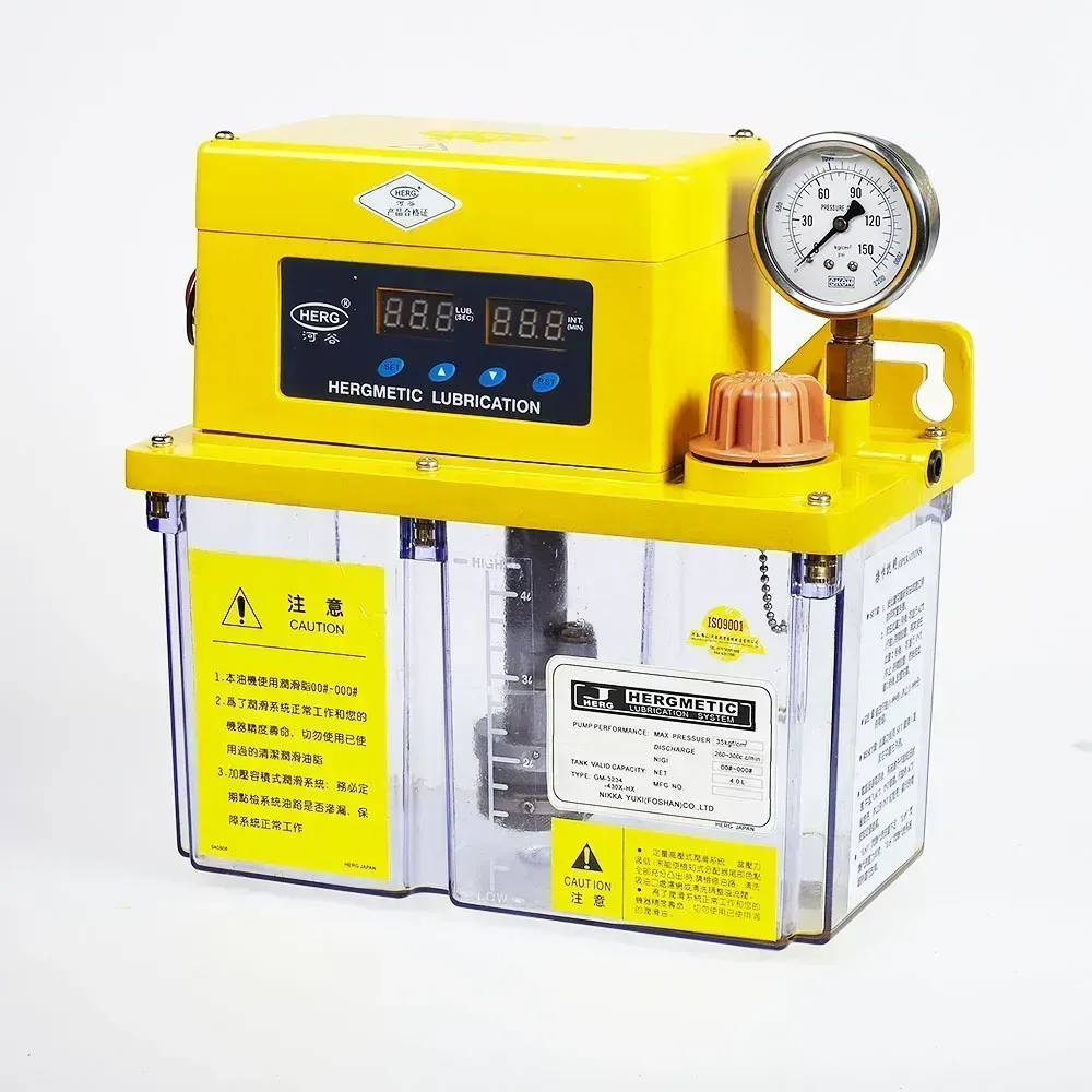 The GM: 3.5 MPa rated output, 30 kgf/cm² pressure-switch action, 2 L or 4 L, PLC terminals on the side.
The GM type grease pump is rated 3.5 MPa (35 kgf/cm²), maximum 5.0 MPa, on NLGI 000# or 00#. Discharge is 260 cc/min at 50 Hz or 300 cc/min at 60 Hz, from a 2 L or 4 L reservoir, on three-phase 380 V. The built-in pressure switch acts at 30 kgf/cm², the floor of the 35-type grease window, so a cycle that never crosses 30 kgf/cm² is a cycle the PLC can call a fault. A 24 VDC level switch covers the other failure: a mechanically fine pump emptying a tank nobody topped up.
Put 35 kgf/cm² at the pump against 30–40 kgf/cm² at the distributor and the pairing is obvious. The GM is not a high-pressure piston pump. It does not need to be. It is the pump whose output sits inside the 35-type's grease action window, which is exactly the clamp circuit above.
Variants: GM-3204 with no on-pump timer (the moulding machine's PLC should own the schedule), GM-3214 with a key-type timer, GM-3234 with the NK-3 display. If the clamp already has a lubrication output, take the 3204 and let the machine run the pump for long enough to reach action pressure, then stop.
The PJ is the middle-pressure alternative: 8.0 MPa, 20 ml/min, 0.3–2.5 L, NLGI 000# to 1#, on AC 220 V, AC 380 V or DC 24 V. Specify it when the run is long, the grade is 0#, or the machine has no 380 V spare for a GM. It is a different pressure class. Do not drop a PJ onto a circuit laid out for a GM, or the reverse, without re-checking the hose, the fittings and the distributor build.
The take-off is not optional on this architecture
A volumetric distributor fills on the fall and fires on the rise. If the pump dead-heads the line and holds it, the chambers never refill and the next cycle delivers nothing. The pressure take-off, the mechanism that relieves the main line when the pump stops, is built into the pump at manufacture. Order it. State "35-type grease" or "34/35 oil" on the enquiry so it is not left off.
Progressive blocks want the opposite: continuous supply, no vent between cycles, because the pistons advance only while flow is present. An SD series clamp circuit is a real and useful build when you want a blocked pin to stall the block and raise a cycle alarm. It is not the same order as a GM-plus-35-type circuit, and you cannot convert one into the other by changing a setting. If you want the proveable-cycle version, that logic is in progressive distributors and PLC monitoring. Order the pump without the take-off, fit the micro-switch, and treat a missed count as a clamp fault, not a warning light.
Laying the points out
Count every pin and bushing with the guards off. A 120-tonne toggle machine is not a 12-point machine just because someone remembers twelve nipples. Hidden pins behind the moving platen are the ones that fail first, because they were never on the circuit.
Group points by cluster, not by leftover outlets. A 5-outlet 355XX next to the moving platen and a 3-outlet 353XX on the fixed side beats one 6-outlet body with a three-metre run to the last pin. Doses are per outlet, so grouping does not force equal volumes: a toggle pin can take 0.3 ml and a guide plate 0.1 ml on the same body.
Leave a spare outlet, capped. The first option a toolroom asks for is a fourth-axis unit or an extra wiper; the first thing a moulding shop asks for is "one more pin we found with the cover off."
Tube is part of the spec. Soft-material fittings strip, and a crushed run under a reinstalled guard is the classic dry-pin fault. Walk every run with your hands before the covers go back, the same way the commissioning checklist asks you to on a machining centre. The plumbing is less romantic than the pump. It is where the circuit actually fails.
What the machine should see
Wire the GM's level switch and pressure switch into the moulding machine's alarm chain, not to a lamp on the pump. A clamp that starts with a dry reservoir, or that runs a cycle which never reaches 30 kgf/cm², should not make parts. That is a cheaper interlock than a scored tie bar.
Prove every point once, at commissioning, by cracking the fitting at the pin, not by watching the gauge. The gauge confirms the main line. It does not confirm the top-right toggle. After that, consumption is your check: a reservoir that empties much faster than points × dose × cycles is a leak; one that barely moves is a pump that is not firing the distributors. The fault tree is the same one in troubleshooting centralised lubrication.
What to send for a parts list
Machine make and tonnage, oil or grease (and the grade if the manual names one), a point count (or a photograph of the clamp with the guards off) and whether the PLC already has a lube output. A nameplate photo of the pump you are replacing is enough when the machine is a reprint of one we have already specced: see our centralised lubrication system replacements for how we configure the pump, distributor, tubing and fittings around the existing clamp.
The design worksheet asks those questions in order. The application page is the short version of the pairings. Neither one requires you to decide between 34-type and 35-type before you write. That is the part we will do from the point list.
Related articles
Technical Guides
CNC Lubrication System Layout: Where the Pump, Lines and Distributors Go
Sizing tells you what to buy; layout decides if you can maintain it. Pump placement, trunk and branch routing, and where distributors must sit.
Technical Guides
When a Centralised Grease System Can Run NLGI 2
NLGI 2 belongs on a 30 MPa progressive circuit, not a GM or 35-type reservoir. The three grease pressure classes decide the grade, and what mixing them costs.
Technical Guides
How to Set Up a Wireless MPG: Workflows That Actually Change
Five setup jobs where a wireless MPG changes how you stand and work, from indicating fixtures to first-part proving, and the habits it asks for.