Technical Guides
Progressive Distributors and PLC Monitoring: Lubrication You Can Prove
AMAG Team7 min read
Most centralised lubrication systems ask you to take delivery on faith: the pump ran, the line reached pressure, so you assume every bearing got its dose. Usually that holds. The times it doesn't are the times that cost a way or a bushing, with nothing in a conventional system warning you first.
Series-progressive is the exception. Done and instrumented properly, it's the one lubrication layout where the control system can prove, cycle by cycle, that every point received lubricant.
The mechanism: a sequence that cannot skip
A series-progressive distributor is a block of metering pistons. Lubricant enters through a single inlet, and internal porting directs it against the first piston, which shifts and displaces a metered slug out of its outlet. Porting then redirects flow to the next piston, and so on in sequence, until the cycle starts over.
The property that matters is this: piston three can't move until piston two finishes, and piston two can't finish unless its outlet took the dose. So a completed cycle isn't a hopeful indicator. It's mechanical evidence that every outlet discharged its metered volume, built into the geometry with no electronics required.
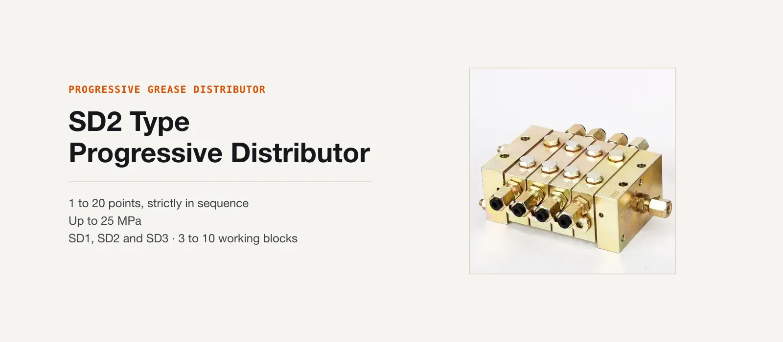
AMAG's SD series block-type progressive grease distributors implement this as modular assemblies: a start block and an end block sandwiching 3 to 10 middle wafer sections, serving 1 to 20 lubrication points per distributor. Dose per point is set by wafer selection. The SD1 delivers 0.08–0.24 ml per cycle from a single outlet, the SD2 0.16–0.40 ml per cycle single outlet, and the SD3 0.40–2.40 ml per cycle from a double outlet.
Maximum working pressure is 25 MPa, with a minimum starting pressure of 1.4 MPa to cycle the pistons. On the SD2, the optimum feed tube is Ø6 mm at 1.5–4.5 m run length, into an Rc1/8 inlet. These are single-line master systems: one supply line in, sequenced metered outputs downstream.
The stall is a feature: if you're listening
The same mechanism that makes delivery provable also produces the architecture's defining trait: one blocked point stalls the entire distributor. If outlet five's bearing has seized its fitting shut, piston five can't displace, the sequence can't advance past it, and the whole block stops cycling. Every point on that distributor stops receiving grease.
At first that sounds like a defect. Compared to a volumetric distributor, where one blocked outlet leaves the rest fed, it can be. But the volumetric system fails silently, starving one point for months while everything else looks normal. The progressive system instead fails loudly, halting a mechanism you can watch or measure. That loud failure tends to get fixed within the week, rather than discovered later at a rebuild.
The critical word is "if." An unmonitored progressive distributor is the worst of both worlds: a stall nobody notices starves twenty points instead of one. It only pays off when instrumented.
Two ways to watch a progressive block
The SD series offers two monitoring options.
The first is a mechanical indicator pin that moves visibly with the piston cycle, giving an operator direct confirmation. It's the progressive-side cousin of the signal pin on our RH3 volumetric distributor (covered in what the RH3 signal pin actually tells you), with the same limitation: it needs a human looking at it.
The second is an electric micro-switch: a contact actuated once per distributor cycle, wired back to the machine's PLC. Now the confirmation is a signal the control system can count, on third shift, in a lights-out cell, on a machine nobody walks past. For unattended equipment, this is the option that matters.
The PLC pattern: from faith to interlock
The logic behind a cycle switch is simple enough to describe without reference to any controller brand. Implement it from your own documentation, not from a blog post.
The pattern is: command lubrication, expect N cycle pulses within a timeout, alarm on a miss. When the lube schedule fires, the PLC energises the pump output and starts a timer. Each time the distributor completes a cycle, the micro-switch gives the PLC one count.
The program needs to know how many cycles constitute a full dose for that machine. That number comes from your point-by-point volume requirements weighed against the per-cycle discharge of the wafers you specified. If the expected count arrives before the timer expires, the cycle is logged good and the pump shuts off. If it expires short, the PLC raises a lubrication fault.
What you do with the fault is a plant decision. You can annunciate it, hold it on the maintenance screen, or treat it as a genuine interlock blocking the next start, the stronger call for expensive spindles and ways. Either way, lubrication stops being something the machine attempts and becomes something it verifies: every completed count is proof every point got its dose.
Building the fully monitored grease system
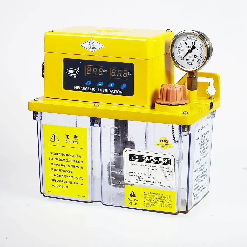 The GM pump: pressure gauge, level switch, and PLC-ready terminals on a transparent reservoir.
The pump is the system's other half. The natural partner for SD-series blocks is the GM type motor-driven grease pump: rated output pressure of 35 kgf/cm², a 2 L or 4 L reservoir, and delivery of NLGI 000# or 00# semi-fluid grease. Those are the grades suited to small-bore lines and distributor valves, for reasons we unpack in why centralised systems use 00 and 000 grease.
The GM brings three PLC-compatible signals. A 24 VDC grease level switch tells the controller the reservoir is running low, catching the case where the system is mechanically fine but pumping from an empty tank. A built-in pressure switch acting at 30 kgf/cm² reports pressure state on the output side, and the distributor's micro-switch reports cycle completion.
Wire all three and the PLC can distinguish faults that would otherwise look identical: low level (refill), pressure present but no cycle counts (a blocked point, covered below), or no pressure rise at all (pump, coupling, or supply-side problem). That's a complete picture of the grease system's health, available on the maintenance screen every cycle.
When the alarm fires: finding the blocked point
The cycle alarm will eventually trip. With the pump running, crack the outlet fittings on the stalled distributor one at a time: open one, watch, close it, move on. When you open the blocked one, the distributor resumes cycling. The indicator pin starts moving again, or the PLC starts receiving counts, and grease discharges from the opened fitting.
The stalled piston is the one whose outlet is blocked, pinned mid-stroke against a line that won't accept fluid. Cracking any other outlet changes nothing, but cracking the blocked one gives it somewhere to displace to, and the sequence unlocks.
The last fitting you opened before cycling resumed is your blocked line. Trace it to the bearing to find out whether the problem is a crushed tube, a seized fitting, or hardened grease at the point. Semi-fluid grease at line pressure makes a mess, so bring rags, and wear eye protection when cracking fittings on a pressurised system.
Where this architecture fits
Progressive monitoring isn't the answer for every machine. A three-point lathe with an attended operator doesn't need a wafer block and a cycle counter. We compare the architectures honestly in lubrication system architectures compared. But for unattended equipment, for grease systems feeding points you can't see, and for any machine where "did it actually lubricate?" needs a machine-readable answer, series-progressive with micro-switch feedback turns the question into a checkable fact.
If you're specifying a system like this (points, doses, wafer counts, pump pairing, monitoring signals), our system design worksheet walks through exactly the inputs we need to lay one out for your machine.
Related articles
Technical Guides
CNC Lubrication System Layout: Where the Pump, Lines and Distributors Go
Sizing tells you what to buy; layout decides if you can maintain it. Pump placement, trunk and branch routing, and where distributors must sit.
Technical Guides
When a Centralised Grease System Can Run NLGI 2
NLGI 2 belongs on a 30 MPa progressive circuit, not a GM or 35-type reservoir. The three grease pressure classes decide the grade, and what mixing them costs.
Technical Guides
How to Lubricate an Injection Moulding Machine: Tie Bars, Toggles, and Platens
Oil or semi-fluid grease on the clamp, why those points want pressure-volumetric metering, and the AMAG pump pairings that match a 35-type action window.