Technical Guides
Sizing a Centralised Lubrication System: A Worked Example
AMAG Team7 min read
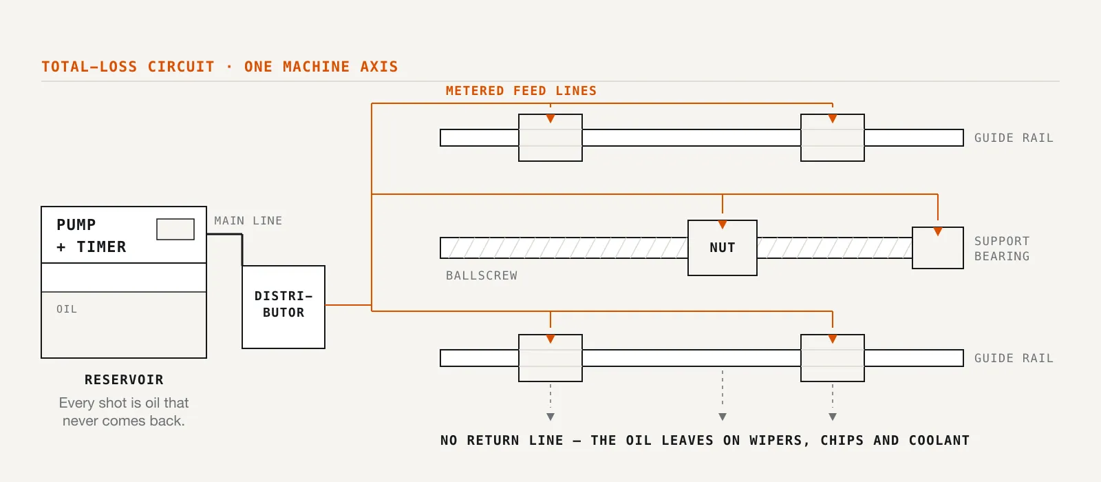
Sizing a lubrication system is mostly arithmetic, and the arithmetic is short. What trips people up is that nobody shows it. Datasheets give component specs but leave assembling them into a system as an exercise. Here's that exercise, worked for one hypothetical machine: a mid-size 3-axis vertical machining centre with oil-lubricated linear guides and ballscrews, running total-loss lubrication from a single pump.
The numbers below are illustrative. Where a machine builder publishes points, doses, and intervals for your machine, that document wins. The value here is the method.
Step 1: Inventory the points
 Walk the machine: every guide truck, ballscrew nut and plumbed bearing on it is a point to count.
Walk the machine and count everything the lubrication circuit reaches, or should. On a typical 3-axis VMC, each axis rides on two linear rails with two guide trucks per rail, each with a ballscrew and lubricated nut. Two of those ballscrews also have plumbed support bearing points at the driven end.
| Point group | Count | Notes |
|---|---|---|
| X-axis guide trucks | 4 | 2 rails × 2 trucks |
| Y-axis guide trucks | 4 | 2 rails × 2 trucks |
| Z-axis guide trucks | 4 | 2 rails × 2 trucks |
| Ballscrew nuts | 3 | one per axis |
| Ballscrew support bearings | 2 | plumbed points, X and Y driven ends |
| Total | 17 |
Resist the urge to round this off from memory. Points hide behind way covers, and the gap between 16 and 17 points can mean a distributor layout that doesn't fit, or a point stuck on manual oiling. Count on the actual machine, covers off if needed.
Step 2: Assign a dose to each point
With a volumetric architecture, each point gets a fixed dose per cycle, so the next job is assigning them. The 35 Type distributor gives 0.1 to 0.6 ml per outlet per cycle. For points needing less than 0.1 ml, the RH3 distributor meters down to 0.03 ml. (Mechanism behind "fixed dose per cycle": how volumetric distributors work.)
The reasoning: a ballscrew nut works under load with recirculating elements in a nearly closed body doing real work, so it sits mid-range. Guide trucks spread the load across four points per axis, so each needs less. Support bearings are lightly loaded and get the minimum. If the machine builder's manual states doses, use those; this table is for when none exists.
| Point group | Count | Dose per cycle | Subtotal |
|---|---|---|---|
| Guide trucks | 12 | 0.15 ml | 1.8 ml |
| Ballscrew nuts | 3 | 0.3 ml | 0.9 ml |
| Support bearings | 2 | 0.1 ml | 0.2 ml |
| Total per cycle | 17 | 2.9 ml |
Step 3: Pick the distributor configuration
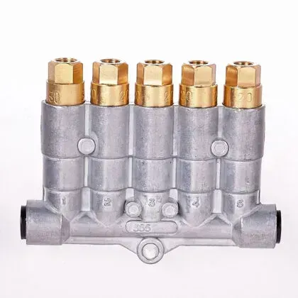 A 5-outlet 35-type body. Doses are set per outlet, so how you group points doesn't constrain the dose table.
Seventeen points want eighteen outlets, since you should leave one spare. The clean answer: three 6-outlet 356XX distributors, 18 outlets, one capped spare for a later fourth-axis unit or extra wiper point. Equally valid: 5- and 3-outlet bodies (355XX and 353XX), each near the cluster it feeds, for shorter lines and easier fault-finding.
Either way, doses are set per outlet, so grouping doesn't constrain the dose table above. The distributors hang on one main line and fire on the same pressure cycle.
Step 4: Cycle volume, interval, and the reservoir
From the dose table, one cycle delivers 2.9 ml across the machine. How often should that happen?
The builder's schedule beats any rule of thumb. Absent one, start conservative and inspect. This is total-loss lubrication, so feedback is visible: oil leaving the system lands in the chip pan and coolant, and over-lubrication shows up as tramp oil outpacing the skimmer and consumption you can't justify. Trim the interval by evidence, not habit. Interval and timer settings get their own treatment in total-loss lubrication timer setup.
Say we start at one cycle every 15 minutes over a full 8-hour shift, which comes to 32 cycles:
32 cycles × 2.9 ml = 92.8 ml per shift, call it 93 ml per day on single-shift work, or about 186 ml per day on two shifts.
That number sizes the reservoir. The TZ pump comes with a 2 L or 4 L reservoir: 2 L lasts about 21 working days at 93 ml a day, or 10–11 days on two shifts. Both work, so the choice is refill cadence. A machine on a monthly PM route wants the 4 L reservoir; one checked weekly is fine with 2 L.
Discharge rate is the other half of the pump question. Standard-flow TZ models deliver 110 ml/min at 50 Hz or 130 ml/min at 60 Hz; high-flow models push 220 or 260 ml/min.
Each cycle, the pump delivers 2.9 ml of dose and raises the line to the 12–15 kgf/cm² action pressure that fires the distributors. The dose itself takes under two seconds at 110 ml/min; the rest builds pressure, driven more by tubing volume, trapped air, and line elasticity than the pump. High-flow models suit long lines and many distributors, but this compact 17-point VMC reaches pressure promptly on standard flow, its 15 kgf/cm² rating near the top of the window with 25 kgf/cm² in reserve.
Step 5: Pump variant, timer, and monitoring
The TZ Type pump family splits along two option lines that map onto how the machine runs.
Timers first. The TZ-2202/TZ-3202 skip the timer; the machine's own control starts and stops the pump, suiting shops where the integrator already owns that logic. The TZ-2212/TZ-3212 add a microcomputer dual-timer module, making the pump self-scheduling, good for retrofits and standalone machines nobody wants to touch. The TZ-2232/TZ-3232 add the NK-3 digital display timer with press buttons, useful during commissioning, when you're adjusting the interval often and want settings visible at a glance. Each variant comes in -2 (2 L) and -4 (4 L) reservoir versions, so timer and reservoir choices are independent.
Second, the pressure take-off mechanism: the TZ can be ordered with or without it, making it compatible with both volumetric and resist-type distribution. The two make opposite demands: volumetric needs pressure to rise, then relieve, so the metering chambers refill; resist-type wants continuous flow whenever the pump runs. Specify the architecture when ordering; here, that's the pressurise-and-vent configuration.
Monitoring rounds out the order. A level switch is standard and should be wired, since an empty reservoir means every point starves at once. The optional pressure switch, at 5 or 10 kgf/cm², covers the other failure mode: a lube cycle that never trips it means the line didn't build pressure (a break, a bad fitting, a dry pump), so the machine alarms instead of running unprotected. On a volumetric system, a healthy pump can coexist with a burst line, so that switch is the cheapest insurance in the bill of materials.
Where the example ends and your machine begins
This walkthrough was deliberately clean: one lubricant, one architecture, seventeen well-behaved points, no fourth axis, no grease. Real machines have quirks: some mix oil ways with a greased component, some have a point only a longer line reaches, and some ship with a schedule that contradicts every rule of thumb, where the factory is right. The method still holds: inventory, dose, layout, cycle volume, interval, pump. Layout is the step this walkthrough skips, and it gets its own treatment in where the pump, lines and distributors go. Rather run your numbers with us? Fill in the design worksheet and we'll design against your actual point list.
Related articles
Technical Guides
CNC Lubrication System Layout: Where the Pump, Lines and Distributors Go
Sizing tells you what to buy; layout decides if you can maintain it. Pump placement, trunk and branch routing, and where distributors must sit.
Technical Guides
When a Centralised Grease System Can Run NLGI 2
NLGI 2 belongs on a 30 MPa progressive circuit, not a GM or 35-type reservoir. The three grease pressure classes decide the grade, and what mixing them costs.
Technical Guides
How to Lubricate an Injection Moulding Machine: Tie Bars, Toggles, and Platens
Oil or semi-fluid grease on the clamp, why those points want pressure-volumetric metering, and the AMAG pump pairings that match a 35-type action window.