Technical Guides
Wireless MPG Integration: What Actually Changes Between Fanuc, Siemens, Mitsubishi, Fagor, and Heidenhain
AMAG Team7 min read
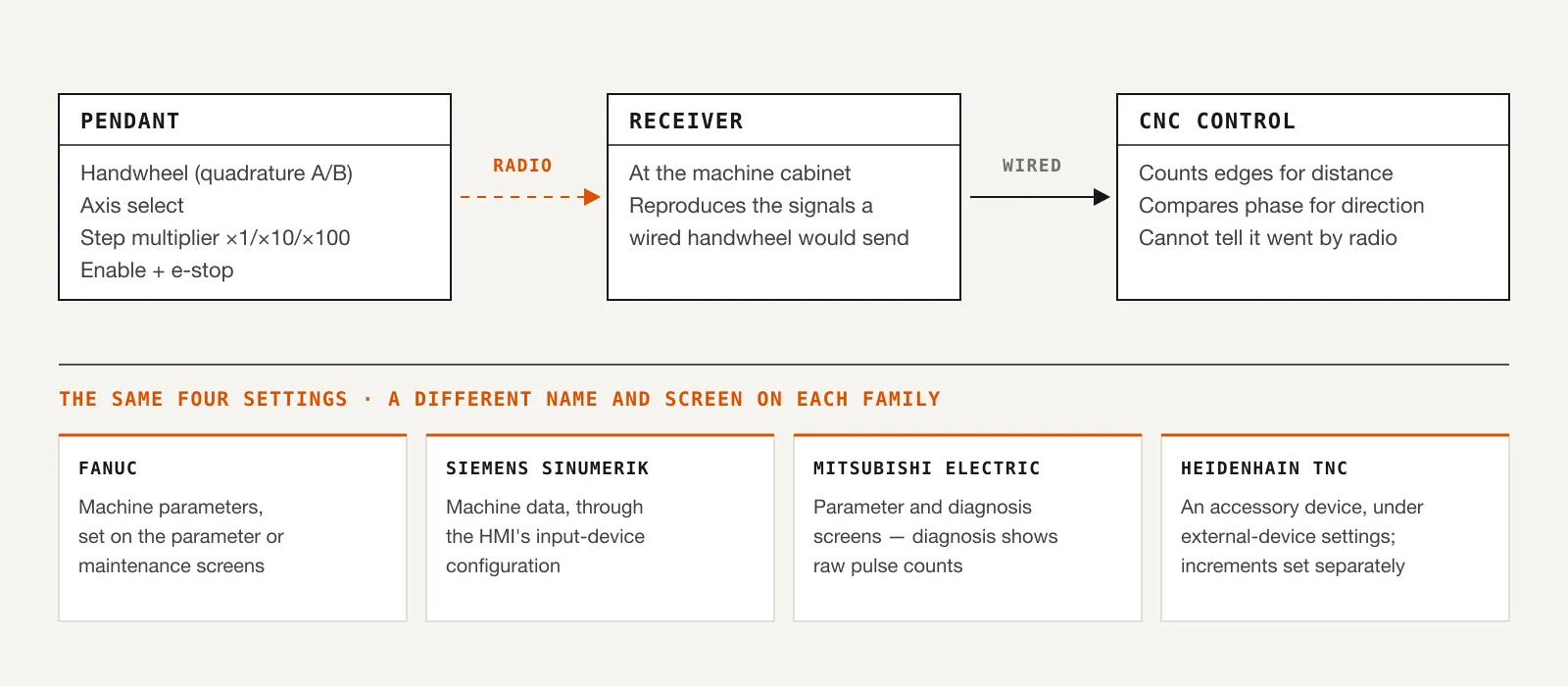
The AMAG Wireless MPG is compatible with Siemens, Fagor, Mitsubishi Electric, Fanuc, and Heidenhain controllers, and that compatibility claim covers real engineering rather than a marketing checkbox. To any of those controls, a properly integrated wireless pendant looks exactly like a wired handwheel: counts, direction, axis selection, and step multiplier arrive the same way they always did. We cover how that translation happens mechanically in how a manual pulse generator works; this post is about the integration itself.
Before touching any hardware, here's the useful reframe: the four things you're configuring are identical across every controller family. What changes is where you configure them and what that screen or parameter is called. You already understand most of the job before you even open a manual.
The four things every integration configures
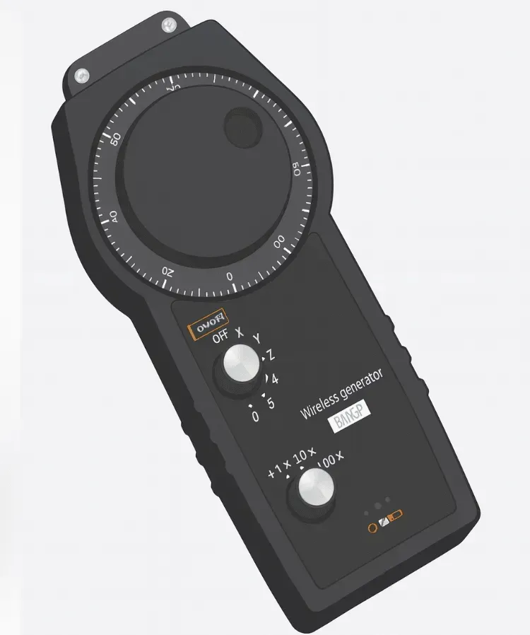 The pendant's axis selector and step multiplier: two of the four mappings your controller has to agree on.
Regardless of brand, a handwheel interface needs the control to agree on four questions, and integration is the process of answering all four correctly.
Direction and distance. The pendant reports wheel motion as a quadrature signal pair, and the control counts edges to get distance and compares phase to get direction. Get the wiring or signal mapping backwards and an axis moves opposite to what the operator expects. That's confirmable, and correctable, during testing.
Which axis responds. The pendant's axis-select switch has to map to the correct physical axis on the machine, not just the correct label. A mislabeled X/Y mapping is invisible until someone is watching the wrong axis move.
How far each detent moves the axis. The step multiplier switch (commonly x1/x10/x100) has to be mapped to real, known distances, and confirmed to be per detent, not doubled, not halved.
Whether motion is permitted at all. The enable/deadman switch and any e-stop on the pendant have to be wired into the control's safety logic so that releasing the enable, or pressing the pendant's e-stop, reliably removes permission for motion. This is the one item on the list worth treating as a hard gate rather than a nice-to-have: don't consider the integration done until this is verified, not just wired.
Before you touch a parameter
Three things belong first, on any controller.
Confirm your specific control accepts external MPG input. Controller families span many software versions, and handwheel-input support and its configuration can differ between them. Identify your controller's exact model and software version before consulting anything.
Get the manufacturer's own documentation for that exact version. This is the one step with no shortcut. Fanuc, Siemens, Mitsubishi, and Heidenhain each publish connection and parameter manuals for their controls, and the correct menu path or parameter number lives in that document for your specific version, not in a general guide like this one. A path that was correct for one software release can be wrong for the next.
Back up your current parameters before changing anything. Standard practice on any CNC work, and non-negotiable here, since handwheel configuration typically touches machine parameters you'll want to be able to restore.
Where the families genuinely differ
The differences between controller brands are real, but they show up in how each vendor organises its menus and names its settings, not in what those settings actually do. Knowing the shape of what you're looking for on each platform gets you through your own manual faster.
Fanuc controls configure handwheel behaviour primarily through machine parameters: numeric parameter settings accessed through the control's parameter or maintenance screens. Expect to find settings governing pulse weighting (how far each detent moves the axis) and axis/direction assignment in that parameter set. The specific parameter numbers and screen navigation are version-dependent; Fanuc's connection manual for your control generation is the authority, not a forum post or a blog written for a different machine.
Siemens SINUMERIK controls handle this more through the HMI's input-device configuration, mapping the external handwheel signal to axis and increment behaviour through machine data rather than a flat parameter list. Fanuc calls it a parameter; Siemens calls it machine data. Either way you're setting which signal drives which axis, at what increment, gated by what safety input.
Mitsubishi Electric controls expose handwheel setup through parameter and diagnosis screens on the control, letting you verify signal reception and assign axes. The diagnosis screen in particular is useful during testing, covered below, because it typically shows raw pulse counts as you turn the wheel. That confirms the pendant is being heard before you worry about whether the mapping is correct.
Heidenhain TNC controls treat an external handwheel as an accessory device, configured through the control's accessories or external-device settings, with increment selection handled separately.
In every case, open your controller's own connection and parameter documentation for your specific model and software version, and use the sections above only to know what you're looking for, not where to click.
Testing before you trust it
However the integration was configured, the verification procedure is genuinely universal, and skipping it is where most real problems come from.
Test one axis at a time, with the machine in a safe state, before assuming all axes are correct. Confirm each axis moves in the direction you'd expect for a positive wheel turn, matched against your machine's actual geometry, not against a memorised convention, since sign conventions vary by machine builder as well as controller.
Confirm the step multiplier is honest. Select x1, turn the wheel a known number of detents, and measure the actual travel against what the setting claims. Repeat at x10 and x100. A multiplier that's off by a factor of ten is an expensive mistake waiting to happen at the worst possible moment, and it's a thirty-second check to rule out.
Confirm the enable/deadman switch actually removes motion permission. Hold it, turn the wheel, verify motion. Release it mid-turn, verify motion stops immediately. Then test the pendant's e-stop the same way. None of this is optional, and shouldn't be assumed just because the pendant "seems to be working." A wheel that jogs correctly with the enable held tells you nothing about what happens when it's released, and that's exactly the case you need to check.
The radio side of the integration
Everything above concerns what the controller does with the signal once it arrives. Whether it arrives cleanly at all is a separate, physical question: receiver placement, antenna position, and distance from drives and welders on the shop floor. That's a big enough topic on its own, and we cover receiver mounting, EMI sources, and how to run a proper coverage test in keeping wireless controls reliable on a noisy shop floor. Do that walk-test during commissioning, not as an afterthought once something feels flaky.
When it's worth a second set of eyes
Some integration problems are genuinely your controller manual's to solve, and some are worth escalating rather than troubleshooting alone: a controller family or software version the documentation doesn't clearly address, a custom or legacy control with non-standard handwheel wiring, or integration across multiple machines that need to behave identically. Contact our technical team with your controller model and software version and we'll work through it with you.
The shape of the job
Every wireless MPG integration, on every controller family, answers the same four questions: direction, axis, increment, and permission to move. Fanuc, Siemens, Mitsubishi, and Heidenhain each ask them through their own screens and their own terms, and only your controller's own documentation tells you what those terms mean for your version. Get the four answers right, verify them with the test sequence above, and the pendant behaves like a wired handwheel from then on.
Related articles
Technical Guides
CNC Lubrication System Layout: Where the Pump, Lines and Distributors Go
Sizing tells you what to buy; layout decides if you can maintain it. Pump placement, trunk and branch routing, and where distributors must sit.
Technical Guides
When a Centralised Grease System Can Run NLGI 2
NLGI 2 belongs on a 30 MPa progressive circuit, not a GM or 35-type reservoir. The three grease pressure classes decide the grade, and what mixing them costs.
Technical Guides
How to Lubricate an Injection Moulding Machine: Tie Bars, Toggles, and Platens
Oil or semi-fluid grease on the clamp, why those points want pressure-volumetric metering, and the AMAG pump pairings that match a 35-type action window.