Maintenance
Complete Guide to CNC Machine Lubrication Systems
AMAG Team8 min read
A CNC machine has dozens of points that need a controlled film of oil or grease to keep running: spindle bearings, linear way guides, ballscrew nuts, tool changers, gearboxes, chucks. Miss one and the failure shows up as wear, not as a warning light: a way that scores, a ballscrew that develops backlash, a bearing that runs hot until it seizes. Automated lubrication exists to make sure that never happens by accident. This guide covers the three metering architectures behind every centralised system, how to match lubricant and pump to the job, and the maintenance habits that keep the whole thing invisible.
Manual Lubrication Still Has a Place, and Also a Ceiling
Some machines are still oiled by hand: an operator with an oil can, working from a lube card, on a schedule they're trusted to keep. It costs nothing to install and works fine on simple machines with a handful of points. It also depends entirely on the operator remembering, and on nobody being short-staffed the week the way lube was due. As point counts rise and duty cycles tighten, manual oiling becomes the least reliable part of the machine, which is why every builder above a certain size specifies an automatic system instead.
The Three Metering Architectures
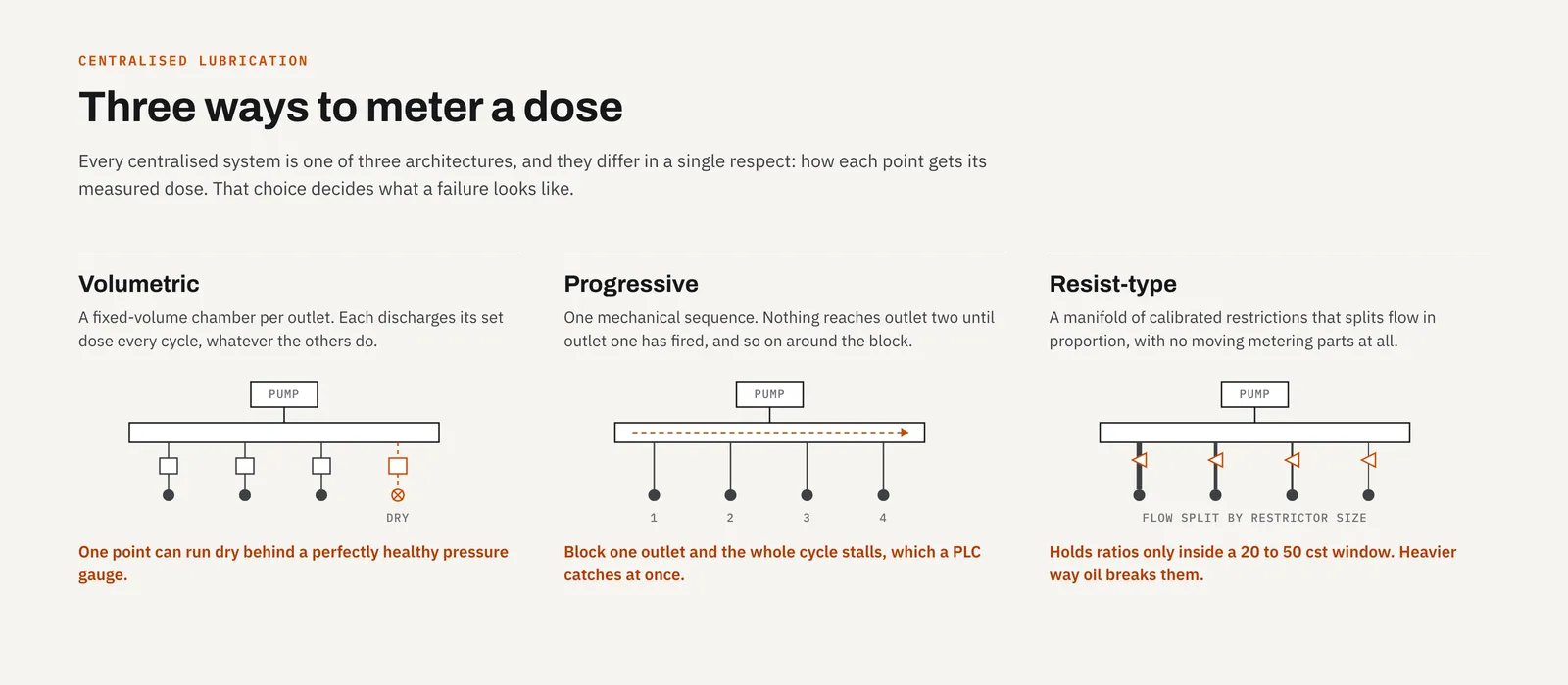
Automated lubrication systems fall into three families, and the difference between them is how each point gets its measured dose.
Volumetric (metering) systems use distributor blocks with a fixed-volume chamber per outlet. Every cycle, each outlet discharges its set dose regardless of what the other outlets are doing. One point can run dry without affecting its neighbours, which is both the architecture's convenience and its blind spot, since a single starved point can hide behind a healthy pressure gauge. The 34-type distributor covers 2–5 outlets at 0.03–0.16 ml per cycle for compact machines; the 35-type steps up to 2–6 outlets at 0.1–0.6 ml and a wider 20–500 cst viscosity window, making it the default for most CNC way and ballscrew circuits. The RH3 distributor adds a built-in signal pin that extends and retracts with each cycle, giving a visual, at-a-glance confirmation that a specific outlet actually fired, useful on machines where a dry point would be expensive to discover the hard way.
Progressive systems wire every outlet into one mechanical sequence: oil or grease has to move through outlet one before outlet two can fire, and so on around the block. Block a single outlet and the whole sequence stalls, which sounds like a liability until you realise what it buys you: a stalled cycle is an alarm condition a PLC can catch immediately, instead of a slow, invisible failure at one point. The SD-series distributor is the modular version of this, built from 3–10 wafers covering 1–20 lubrication points at up to 25 MPa, common on heavy CNC centres and injection-moulding platens. The U-shaped distributor packages 4–12 points into one body at a fixed 0.3 ml per point, with an optional cycling feedback switch for PLC monitoring. The mechanics of that monitoring are covered in progressive distributors and PLC monitoring.
Resist-type (proportional) systems are the simplest and cheapest of the three: a manifold of calibrated restrictions that splits flow proportionally to each point's restrictor size, with no moving metering parts at all. The TCJ/TCZ family offers five graded flow sizes for oil circuits, but only within a 20–50 cst viscosity window: heavier way oil breaks the intended flow ratios, which is one reason resist-type systems suit light machinery rather than a slideway running VG 220. Full detail on how metering, progressive, and resist-type systems actually differ mechanically is in lubrication system architectures compared.
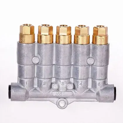 The 35-type: 2 to 6 outlets, 0.1–0.6 ml per cycle, the volumetric distributor behind most CNC way and ballscrew circuits.
Matching Lubricant to the System
Getting the right lubricant into the right hardware matters as much as picking the architecture. Machine tool oils are graded by ISO viscosity (VG 32 and VG 46 for hydraulics, VG 68 and VG 220 for slideways), and every distributor and pump has its own viscosity window: a 35-type accepts 20–500 cst, wide enough for any common way oil, while TCJ/TCZ resist distributors top out at 50 cst. Slideway oil isn't just thick oil, either: it carries tackifiers and boundary-lubrication additives that plain hydraulic oil lacks, which is why substituting one for the other shows up weeks later as stick-slip and wear rather than an immediate failure. The full reasoning is in our machine tool oil viscosity guide.
Grease systems have the equivalent constraint in NLGI grade. Volumetric grease pumps like the GM run NLGI 000# or 00# semi-fluid grease only: a stiffer grade will stall the metering valves. High-pressure progressive pumps like the ZJ and ZD are rated up to NLGI 2#, but only because the progressive architecture pushes grease at full pump pressure rather than through a small metering chamber. Mixing grades across those pressure classes is the single most common grease-system specification error; see when a centralised grease system can run NLGI 2 for the full breakdown.
Pumps: Matching the Drive to the Demand
Oil pumps and grease pumps are sized by reservoir, pressure, and discharge rate. The TZ Type oil pump is the general-purpose workhorse: 2L or 4L reservoir, 15 kgf/cm² rated pressure, 110–260 ml/min discharge depending on model, with a choice of no timer, a built-in dual-timer module, or the NK-3 digital display for on-machine adjustment. The HL Type covers the same territory at a slightly higher flow ceiling. On the grease side, the GM Type is the motor-driven pump most volumetric grease circuits are built around, while the PJ series and vehicle-supply AP pump cover lighter and mobile applications respectively. Every pump family also comes in a manual hand-pump variant for circuits with no electrical supply nearby.
Sizing a System: The Short Version
Sizing is arithmetic once you have three numbers: how many points, what dose each one needs, and how often the cycle should run. Count every point on the actual machine (points hide behind way covers), assign a dose based on load and duty, and multiply out to a cycle volume. That volume, divided into the pump's reservoir capacity, sets your refill interval: a 2L reservoir feeding a modest 17-point machine at roughly 93 ml a day lasts about three weeks. We walk through the full calculation, point by point, in sizing a centralised lubrication system: a worked example.
Maintenance Schedule
- Daily/Weekly: Check lubricant levels, confirm the level switch is wired into the alarm chain (not just present), and glance over hoses and fittings for weeping or wet spots.
- Monthly: Inspect hose runs and connections along their full length, not just at the ends, and test the pressure switch by simulating a fault rather than assuming it works.
- Quarterly: Clean or replace filters, and record the system's time-to-pressure against its commissioning baseline; both too-fast and too-slow indicate a fault. See our commissioning checklist for how to establish that baseline in the first place.
- Annually: Full system inspection, pump bench test if pressure is marginal, distributor inspection on any point with a history of running dry, and a review of dose and interval settings against actual machining hours.
Common Mistakes to Avoid
- Using the wrong viscosity or grease grade for the hardware: every distributor and pump publishes a window; running outside it stalls metering valves or breaks flow proportions.
- Over-lubrication, which wastes lubricant and, on total-loss oil systems, shows up as tramp oil outpacing the coolant skimmer.
- Under-lubrication from an unmonitored dry point: the volumetric architecture's blind spot, where one starved outlet hides behind a healthy pressure gauge until a bearing or way shows wear.
- Ignoring filter and contamination discipline. Most jammed metering valves trace back to grit entering through an open reservoir lid or a dirty transfer container. The fix is boring and effective: dedicated clean containers, lids closed, sealed source oil.
- Mixing incompatible lubricants, including mixing grease pressure classes (semi-fluid grease into a high-pressure progressive pump, or vice versa) and blending oil viscosity grades, which produces a fluid matching no specification.
Conclusion
The right lubrication system isn't the most expensive one: it's the one whose architecture, pump, and lubricant all agree with each other and with your machine's actual point count and duty cycle. Get that match right and the system disappears into the background, doing its job cycle after cycle without anyone thinking about it. If you're specifying a new system or troubleshooting an existing one, our troubleshooting guide covers the common fault signatures, and our full product range covers every distributor, pump, and pressure class discussed here. When the diagnosis is that the pump or distributor is past its working life rather than one fault away from fixed, see our centralised lubrication system replacements for how we pair a new pump and distributor around the machine you already have.
Explore our lubrication systems or contact us today to find the perfect solution for your equipment.
Related articles
Maintenance
Keeping Wireless Controls Reliable on a Noisy Shop Floor
Why machine shops are hard on radio links, and how receiver placement, cable routing, and honest battery habits keep a wireless pendant dependable.
Maintenance
Commissioning a Lubrication System: From First Fill to First Cycle
A step-by-step commissioning sequence for centralised lubrication, from a clean first fill to proven oil delivery at every single point.
Maintenance
Troubleshooting a Centralised Lubrication System, Fault by Fault
A symptom-first guide to centralised lubrication faults: pressure problems, dry points, stalled progressive blocks, and alarms that never fire.